Switching vs. Linear Regulators
<<BackSource:Edadoc Time:2018/9/17
We will analyze the pros and cons of Switching regulators (DC-to-DC) and Linear regulators (LDO) in order to determine the best option for PCB Design. DC Power is characterized by type, circuit structure and topology. It can be categorized into linear type, switch type, SCR rectifier or induction type. Some are classified into chemical power supply, linear power supply and switching power supply. Other classifications simply divide them into two: linear and switch type.
An LDO regulator is a DC Linear regulator. It can regulate the output voltage when the input voltage is a small amount higher than the desired output voltage. A DC-DC regulator is a Switching regulator. It involves rapidly switching a device on and off in order to achieve the desired output voltage.
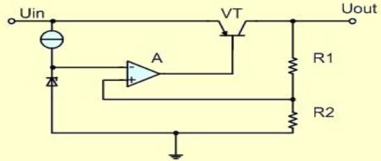
[A LDO (Low Dropout Regulator) has the following internal structure:]

The components used are relatively simple: a series adjustment tube (VT), two voltage divider resistors (R1, R2), an amplifier (A), and a reference voltage (REF). The R1 and R2 resistors are connected to the amplifier, which is connected to the reference voltage. The output of the amplifier (A) is used to drive the adjustment tube (VT), and the input & output of the adjustment tube are connected to the input & output of the circuit.
How does this regulate the voltage? Here is the working principle:
When the output voltage (Uout) falls, the sampling voltage divided by R1 and R2 (ie. The non-inverting input voltage of the amplifier) decreases. This means the output drive current of the amplifier (A) increases, resulting in a decrease in the voltage across the regulator tube (VT). This will make Uin-Uout decrease and eventually make Uout voltage rise. This feedback mechanism is what stabilizes the system.
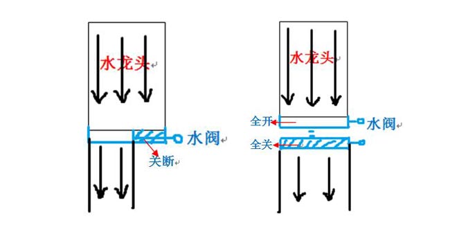
If this is still confusing, think of the LDO regulator as a large faucet system. Our goal is to get a smaller flow (output voltage) from this large faucet (input voltage). We have two ways in which to accomplish this:

The left side of the diagram illustrates the functions of a LDO regulator. The water valve is in a fixed position that releases the exact amount of water we need. The right side illustrates the functions of a DC-DC regulator. The water is passed through the faucet while it’s either completely open or completely closed. By alternating how often the faucet is open or closed, we can control the size of the stream. This is the difference between LDO and DC-DC power supply.
An LDO regulator is a DC Linear regulator. It can regulate the output voltage when the input voltage is a small amount higher than the desired output voltage. A DC-DC regulator is a Switching regulator. It involves rapidly switching a device on and off in order to achieve the desired output voltage.
[A LDO (Low Dropout Regulator) has the following internal structure:]

The components used are relatively simple: a series adjustment tube (VT), two voltage divider resistors (R1, R2), an amplifier (A), and a reference voltage (REF). The R1 and R2 resistors are connected to the amplifier, which is connected to the reference voltage. The output of the amplifier (A) is used to drive the adjustment tube (VT), and the input & output of the adjustment tube are connected to the input & output of the circuit.
How does this regulate the voltage? Here is the working principle:
When the output voltage (Uout) falls, the sampling voltage divided by R1 and R2 (ie. The non-inverting input voltage of the amplifier) decreases. This means the output drive current of the amplifier (A) increases, resulting in a decrease in the voltage across the regulator tube (VT). This will make Uin-Uout decrease and eventually make Uout voltage rise. This feedback mechanism is what stabilizes the system.
If this is still confusing, think of the LDO regulator as a large faucet system. Our goal is to get a smaller flow (output voltage) from this large faucet (input voltage). We have two ways in which to accomplish this:

The left side of the diagram illustrates the functions of a LDO regulator. The water valve is in a fixed position that releases the exact amount of water we need. The right side illustrates the functions of a DC-DC regulator. The water is passed through the faucet while it’s either completely open or completely closed. By alternating how often the faucet is open or closed, we can control the size of the stream. This is the difference between LDO and DC-DC power supply.


